
How Does a Strain Gauge Measure Real Force in Materials Testing?
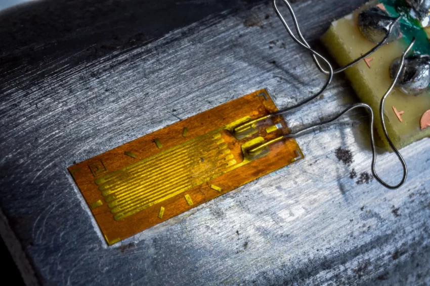
Materials testing begins with a simple question: how does a specimen bear load before it bends, cracks, yields, or breaks? Force readings from a test frame help, but they do not capture the local behaviour on the surface. A strain gauge fills that gap. It detects tiny dimensional changes at a selected point, giving engineers a clearer view of stress distribution, stiffness, and failure development during controlled laboratory loading.
What It Senses
During tensile, compression, or bending work, a strain gauge measures strain rather than force itself. The bonded sensor follows surface movement as the specimen lengthens or shortens under applied load. That localised change helps technicians connect machine force with actual material response, especially where geometry, joints, or fibres create uneven stress patterns.
Basic Working Principle
Most strain gauges use a fine metallic foil grid fixed to an insulating backing. The assembly is bonded to a prepared specimen surface. When the material stretches, the foil elongates with it, changing electrical resistance. Compression shortens the grid and shifts resistance in the opposite direction. This small change in electrical resistance can be quantified and converted into a usable strain value through precise measurement.
From Strain to Force
Force is calculated through mechanics. The test machine applies load through calibrated components, while the gauge captures local deformation. Engineers combine specimen area, geometry, elastic modulus, and fixture details to establish the relationship between strain and stress. Once the stress is known, force can be checked against the loaded cross-section and machine data.
Why Bonding Matters
Bond quality decides whether the reading can be trusted. The gauge must follow the specimen surface without sliding, lifting, or lagging. Cleaning removes oil and residue. Light abrasion improves adhesion. Ensuring the correct thickness of the adhesive and allowing for adequate curing time are vital for optimal signal transfer. If the bond layer is poor, the foil may register adhesive movement instead of true material strain.
Electrical Signal Path
The resistance shift is tiny, so the signal needs careful handling. A Wheatstone bridge converts resistance change into voltage output. Signal conditioning then amplifies, filters, and stabilises that output before recording. Variations in temperature can impact resistance, so the configuration of the bridge and compensation strategies are crucial. Shielded wiring, stable excitation, and clean connections reduce noise that could mask deformation.
Common Test Uses
Strain gauges are commonly used in tensile coupons, bending beams, compression blocks, and fatigue specimens. They are also used inside load cells, where controlled elastic deformation creates repeatable force measurement. In a materials lab, a gauge can confirm strain near a hole, weld, adhesive joint, or laminate edge. It can also expose fixture misalignment before results become misleading.
Accuracy Factors
Accuracy depends on several practical details. Gauge factor, alignment, adhesive behaviour, cable routing, temperature drift, and surface preparation all affect results. A sensor placed off-axis may register less strain than the material actually experiences. Heat can create apparent strain without added load. To ensure reliability, it is essential to conduct calibration checks, maintain stable conditions, and keep written setup records.
Real Force In Practice
A single gauge does not measure total force like a scale. It reports strain at its exact bonded location. Real force becomes clearer when that local value is interpreted alongside load cell output and specimen dimensions. This paired evidence helps separate machine behaviour from material behaviour, which is crucial for understanding the properties of metals, plastics, composites, bonded assemblies, and safety-critical parts.
Data Interpretation
Useful interpretation starts by comparing strain traces with load curves. A straight region usually indicates elastic behaviour. A slope change may suggest yielding, cracking, grip slip, or fixture movement. Repeat tests help confirm whether the pattern is due to the material or the setup. Engineers then use the evidence to inform design limits, validate models, and make decisions.
Conclusion
A strain gauge measures real force indirectly by tracking surface strain with high sensitivity and repeatability. Its strength lies in the chain between deformation, resistance change, and mechanical calculation. When placement, bonding, circuitry, and calibration are controlled, the readings become reliable evidence. Materials testing teams can see where strain accumulates, how load is distributed, and when performance begins to change.


Leave a Reply